
Filters are widely used in RF systems and can be classified based on their structural forms, such as LC filters, dielectric filters, cavity filters, microstrip filters, and waveguide filters. Cavity filters, in particular, offer advantages such as high Q-factor, low insertion loss, and high power capacity, making them widely used in communication systems. This article mainly discusses the design process of cavity filters, which generally includes the following steps:
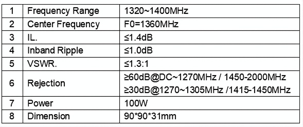
- Analyze Specifications: The first step is to define the filter’s performance metrics, such as frequency range (center frequency, bandwidth), in-band insertion loss, out-of-band suppression, in-band standing wave, port impedance, power capacity, product dimensions, etc. For example, the specifications of our band-pass filter FSBP-1320-1400-30-N are as follows:
- Comprehensive Analysis Using Tools: After defining the filter’s specifications, tools such as CoupleFil, ADS, AWR, CST, etc., are used for comprehensive analysis to determine the filter’s order, whether zeros are needed, coupling coefficients, port Q-factor, etc., thereby defining the filter’s topology.
- 3D Modeling and Simulation: Based on the results of the comprehensive analysis, 3D modeling and simulation of the filter begin. Common simulation methods for 3D modeling include HFSS, CST, and others. These methods include single-cavity simulation, dual-cavity coupling simulation, port delay simulation, overall model simulation, and optimization. After obtaining the initial model, further optimization is necessary. The simulation results from HFSS are exported as .s2p files and imported into CST Filter Designer for fitting. This allows viewing the deviation of each parameter, and the physical dimensions can be adjusted accordingly. After several iterations, the final model dimensions and simulation curve are determined.
After modeling and simulation optimization, the entire design process of the cavity filter is completed. For actual production of the cavity filter, the structure from the simulation design can be used for fabrication drawings, including the cavity, cover plate, RF connector selection, surface treatment specifications, etc. In practical applications, the structure of the filter is more complex, and engineering applications need to consider the feasibility of final manufacturing, production costs, and ease of adjustment, among other factors.